

This is a clone of the original Dance Dance Revolution GN845-PWB(B) Stage I/O board.
Overview
This board was designed as a drop in replacement for the Konami GN845-PWB(B) Stage I/O board.
Check out the FAQs for answers to a lot of common questions.
Check out the installation guide for more information on how to connect it.
Please note the current firmware does not support SuperNOVA cabinets that use Python 2.
This board emulates the original DDR Stage I/O communication protocol boot sequence allowing to run the game without an IO Check Bypass. Sensor masking is also supported.
It also provides additional features such as debouncing and a Light-On-Press mode that lights up the arrow light when pressed without the need of an external lights driver board.
The board can also be re-programmed with a custom/updated firmware.
Tech specs
| Input voltage (recommended) | 12V |
| Input voltage (limit) | 9-15V |
| Power consumption (idle) Calculated when the board is idle with all lights and sensors off | 0.22W |
| Light power (max) @ +12V | 15W |
| Light driver current (max) | 1.25A |
| Output response time (max) This is the time required for the output to react to a change of a sensor input | 50uS |
| Width | 110mm |
| Length | 185mm |
| Height | 15mm |
| Weight | 90gr |
| Mounting hole diameter | 4mm |
| Product code | 9846 |
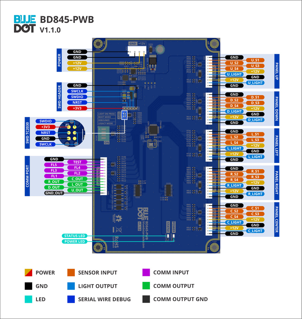
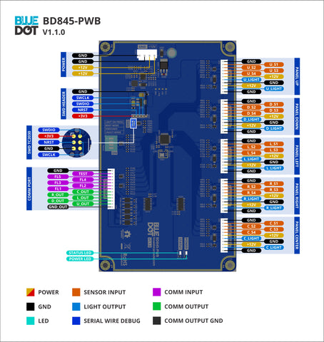
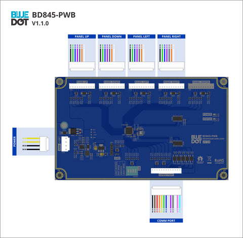
Pinout diagram

DIP switches
On the bottom side of the board there are four DIP switches that allows you to configure some of the board parameters.
To turn ON an option put the corresponding toggle in the up position corresponding to the ON text. The lower position corresponds to OFF.
Check the installation guide to know the proper configuration based on your cabinet setup.

Light on press
When ON the panel light will light up when the panel is pressed. This way you don’t need an external lights driver.
When OFF the lights will be controlled by the external lights driver which can be, for example, the KSYS573 for original DDR games or a LumenAR for Stepmania setups
Boot mode
When ON the BOOT0 pin of the STM32 MCU will be tied to +3V3. This puts the board into a forced program mode.
When OFF the BOOT0 pin of the STM32 MCU will be tied to GND. This puts the board into run mode.
In almost any case this must be set to OFF. Refer to the official STM32 documentation for more information about the BOOT0 pin.
If this option is set to ON the board will not work! For normal operation it must be set to OFF.
Debounce
When ON the sensor debouncing will be enabled. When sensors are released they will still be considered pressed for an additional 4 milliseconds.
When OFF the sensor debouncing will be disabled.
Some games like Stepmania supports software debouncing. If software debouncing is performed by the game already it is recommended to set this option OFF
Legacy mode
When ON the board will listen for original DDR boot command and reply to it. This is required to pass the IO Check on original DDR games.
When OFF the board will ignore the DDR boot command.
More Information:
Read the installation guide for more information on proper installation. Read the FAQs which provides the answer to a lot of common questions.
~If for any reason you are not happy with the part you can get a full refund within 30 days of purchase~