Cobalt Flux Style DIY Pad Guide
Click here to see our Cobalt Flux DIY Kit
Guide for Building the DIY Cobalt Flux Pad
Required tools:
- Phillips head screwdriver
- Power drill, 7/64” drill bit
- Access to a precision saw capable of cutting your wooden base to size
Optional considerations:
- Sandpaper to smooth the edges of the wooden base
- Scotch tape to hold wires in place during setup
- Wood router for cable management
- Tile spacers to help keep panels evenly spaced (see step 4a for more info)
1) Preparing the wooden base
a) Cutting to size
Your wooden base is the most crucial piece in the build, and cutting it to the correct size is extremely important. The first question to ask is how much of a gap do you want between panels? Anywhere from 1/8th to 1/16th of an inch is advisable.
- If 1/16th inch, cut your wooden base to 33 ¼” x 33 ¼” x ¾”.
- If 1/8th inch, cut your base slightly larger at 33 ½” x 33 ½” x ¾”.
This is to ensure there is no panel overhang which could lead to damage of the panels.
Keep in mind, big box stores like Lowes and Home Depot normally DO NOT have the ability to make precision cuts. Their saw is meant to roughly cut wood for the sole purpose of fitting it into your vehicle. You can, however, rent power tools from most hardware stores for cheap. Some local stores may even be willing to do the work for you.
b) Cable management: Routing or drilling?
The next consideration is how you will deal with wiring. There are two options.
- Use a router to dig a small channel into your wooden base to run wires through.
- Drill holes straight through the wooden base, then run your wires underneath and out the bottom of the base.
Routing is safer long term, as it puts less pressure on the cables. Whether or not this matters depends on how hard the surface underneath the pad will be and how often you plan to move your pad.
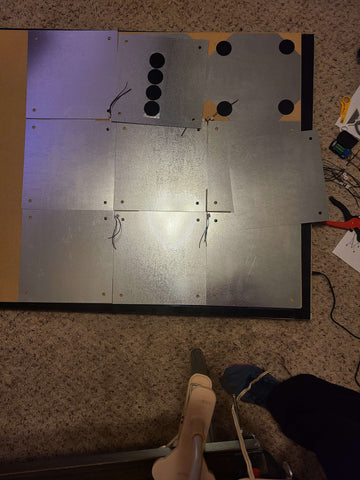
If you choose to use a router, ensure a minimum channel size of 1/2 cm deep by 7/10 cm wide to fit all 12 wires. View the accompanying photos for more details.
2) Wiring
a) How to wire the D-Sub breakout board
To connect a wire to the D-Sub breakout board, carefully strip about 1 cm of the insulating layer to reveal the inner strands of copper wire. Don’t worry if you lose some of the copper strands in the process, as long as the majority of the strands remain intact. Loosen the screw above the pin you want to connect, then insert the wire and tighten the screw to secure it. Do this one wire at a time and, to avoid confusion between wires, make sure to follow step 2b below for each wire.
b) Laying the wires
Using the provided pin out diagram, connect each wire and run it to where the corresponding panel will be. For your convenience, use scotch tape to hold the end of each wire in place on the wooden base, and use a marker to specify the wire pin number. This will be important during step 4b.
Keep in mind, Select and Start do not have dedicated panels. If your intended use case is classic DDR with up down left and right arrows, you will likely want to wire Select and Start to the top-left and top-right panels, alongside their actual directional equivalents. If you prefer Pump It Up style diagonal arrows, consider routing Select and Start to the Left and Right panels. Regardless of your choice, you can always rebind your panels in-game to customize the pad to your liking. Nothing is permanent.
3) Mounting the stainless-steel grounding base
Do your best to place the stainless-steel grounding base in the center of the wooden base, so it’s even on all sides. It does NOT need to be perfect, as long as it looks fine to you. Once you’re happy with the placement, grab the prickly half of the Velcro mounting adhesives and attach them as shown. Again, this does not need to be perfect. Aim to have slightly over half of the adhesive touching the wooden base.
Please note, the grounding wire should be stripped and attached to the grounding base by Velcro adhesive.
4) Mounting the stainless-steel panels
a) Tile spacers
In order to properly space out each panel, tile spacers are recommended. You can likely pick up a pack for a few dollars in the same place you would buy your wooden base. While optional, they make it much easier to keep the panels evenly spaced on all sides. The size you want would be between 1/8th and 1/16th inch, as chosen in step 1a.
b) Attaching the Velcro mounting adhesives
Lay out the stainless-steel panels in a 3x3 grid pattern on top of the grounding base. Try to keep even spacing between each panel. If you have tile spacers, place them at each corner to make this easier. Once you’re happy with the look, choose a corner panel to start with.
Remove the panel and start by stripping the corresponding wire. The goal is to use the fuzzy Velcro adhesive to attach the bare copper wire to a corner of the panel. Make sure the wire isn’t showing through the screw hole, as this could damage the connection. Once attached, apply Velcro adhesives to the remaining three corners, then flip the panel over and attach it to the grounding base. Try your best to maintain even spacing between panels. Repeat this process for every panel.
5) Attaching the clear polycarbonate panels
a) Preparing the clear polycarbonate panels
For each clear polycarbonate panel, peel the protective sticker from one side. Place each panel on top of a stainless-steel panel, ensuring even spacing is maintained.
b) Drilling the holes
Grab a clear corner panel and peel the remaining protective sticker, then place that side face down. Drill out 4 screw holes halfway through the wooden base in clockwise order. As each hole is drilled, test alignment by inserting a screw with a screwdriver. This will also help keep the panel in place as you continue drilling holes.
If a screw pulls the panel off-center, that means the drill hole was not properly aligned. Generally, this shouldn’t be a problem but you can correct this by unscrewing and temporarily skipping this hole. Be extra careful to align the next screw holes properly. Remember to screw in the problem screw when finished with that panel.
Example Build 1


Example Build 2


Classic Cobalt Flux Design


Diagram


